
|
| You are here: Home > DM HVAC > Support > Latest Release and Release History > DM HVAC 5.0 | ||||||||||||||||||||
Design Master HVAC 5.0 General ChangesReleased September 25, 2006. Design Master HVAC 5.0 is a major new release that includes lots of exciting new improvements. Instructions on how to upgrade an existing installation from DM HVAC 4.5 to DM HVAC 5.0. Load CalculationsAutoCAD CommandsAll Design Master HVAC entities now behave like normal AutoCAD entities. You can move, copy, erase, and otherwise modify them with normal commands. All of the changes will be properly registered in the database as you make them. The Diffuser and Duct toolbars have been updated because many of the former commands are no longer needed. Instead of using the Move Diffuser command, you use the AutoCAD move command. As a result of this change:
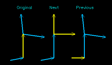
DraftingAutomatic Double-Line UpdateDouble-line ductwork is automatically updated when the ducts are modified. Modifications include removing ductwork, moving ductwork, and changing ductwork properties, such as airflow. Throw ArrowsThrow arrows are now toggled on and off using the Insert Throw Arrow and Remove Throw Arrow commands. You can copy a throw arrow arrangement using the Match Throw Arrow command. Straighten Next / PreviousThe Straighten Duct and Normalize Duct commands have been replaced with two new commands, Straighten Next Ducts and Straighten Previous Ducts. In this example, the original ductwork is shown on the left. The yellow duct on the left is the one that is selected for the two straighten commands. When it is selected for a Straighten Next Ducts command, the two ducts that it points to our straightened. When it is selected for a Straighten Previous Ducts command, the duct that points to it is straightened.
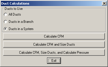
The ducts that are straightened are modified to be either parallel or perpendicular to the selected duct, depending upon with angle to which they were closer to begin. Calculation ChangesDuctwork Calculations CommandThe Ductwork Calculations command has been modified in this release. The six buttons it previously had have been replaced by three choices and three buttons.
The three choices determine which ducts will be used in the calculation.
The three buttons determine which calculation is run on the selected ducts. The different calculation options exist because each one takes progressively longer as you move down the list.
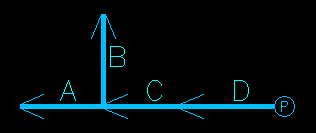
CFM DiversityThe calculation used for CFM Diversity was changed in this release. In both the old and the new releases, the CFM in a duct is equal to the CFM times the diversity factor. Previously, this updated CFM is what was passed to the connected duct. Now, the original CFM is passed to the connected duct. The following example demonstrates the difference between the old and new diversity calculation.
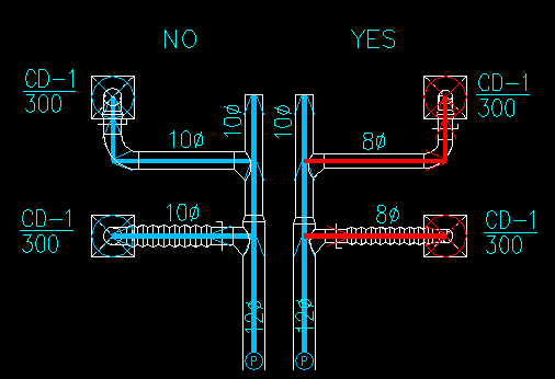
Diffuser Runout SizingThere is a new option available under Diffuser Connections called Size Diffuser Runout to Match Diffuser Neck Size. When Set to NoThe previous version of Design Master worked as if this option was always set to No. All ducts are sized based upon the specified sizing criteria. When Set to YesWhen it is set to Yes, the runouts to diffusers ignore the sizing criteria and instead match their size to the diffuser neck size. A diffuser runout is defined as all the ducts connected from a diffuser to the first branch. The ducts on the left side of this example were sized with this option set to No. The ducts on the right side were sized with this option set to Yes. The red ducts are the ones that were sized to match the neck size of the connected diffusers.
Set CFM Total
When updating the CFM total, all three have the option to pro-rate the CFM change, or average the CFM change. Consider an area that has two diffusers in it, one with 100 CFM, and the other with 200 CFM. If the airflow is increased from 300 CFM to 600 CFM, what should the new airflow values in the two diffusers be?
Usability ChangesCustomizationAll customization has been moved out of TXT files and into the database. To edit the customization, you now use the DM HVAC->Customization commands instead of editing the TXT file manually. Entity Selection on the DrawingWhen selecting ducts or diffusers on the drawing, you no longer draw a box around the item you want. Instead, you select the item with a single click. If there are other non-Design Master entities in the area, they will be filtered out, and the appropriate item will be selected.
|
 There are three commands in this release that can be used to change the CFM total in a group of diffusers. Two of them are not new, but they were buried in the menus and infrequently used. In the new release, they have been made more visible and greatly improved.
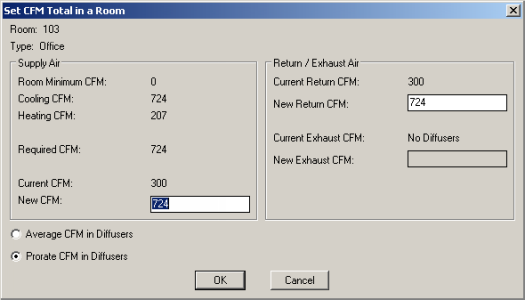
 Editing Schedules
|
HVAC - Electrical - Company
Search - Site Map Contact Info - 1.866.516.9497 - Email Us Subscribe to Newsletter ©2004-7, Design Master Software, Inc |